This post features my personal learnings while replicating networking research and using eBPF. For a more technical description of the work and reproduction strategy, you can find our final report on the reproducing networking research blog.
Stanford University’s computer science curriculum is seemingly split between three main categories: the 1xx courses are geared towards undergraduates, focusing on implementation of solved problems; the 2xx courses are designed for early graduate students (masters in my case) with an emphasis on reading and interacting with existing research; and the 3xx courses are designed for later graduate students (primarily PhDs) with many focused on producing research. There are, of course, all sorts of major exceptions to this rule (i.e. most AI courses are in the 22x series).
In my last quarter at Stanford, I took CS 244: Advanced Topics in Networking which follows this general rule, reading ~30 papers over the span of 10 weeks. What makes 244 unique compared to other courses1 is that students also have to select and replicate a major (i.e. published in a peer-reviewed conference) networking research work and corroborate the findings. The ACM makes a clear distinction between the three categories of “recreating” research:
- Repeatability: same team, same setup
- Reproducibility: different team, same setup
- Replicability: different team, different setup
Setup refers to any artifacts (source code, testing/analysis scripts, input/output data) produced by the authors. In our case, as we’re tasked with replicating a result, we must produce new code and experimental setup based purely on the paper in question.2
For a variety of reasons (mainly recency and relative ease of replication3), we chose to work on ONCache (Lin et al.) from NSDI ‘25. Compared to standard overlay networks for Kubernetes, ONCache claims to improve throughput and request-response transaction rate “by 12% and 36% for TCP (20% and 34% for UDP), respectively.” However, to understand this result, we must first define what Kubernetes is in the first place and examine how it handles networking.
This post is a brief introduction to Kubernetes, how it handles networking, and how overlay networks work with a focus on the encapsulation protocols. The next post will be a deep dive into ONCache and how it achieves its performance improvements, our replication strategy, and our results.
What is Kubernetes?
This introduction is designed to cater to people unfamiliar with Kubernetes (often shortened to K8s) or CS systems as a whole. If you already know what K8s is and how cross-node networking works, you can likely skip this section or you can correct me on what I get wrong :)
In the beginning of computation, most systems were single-tenant and only supported one application at a time. Later computers improved on this, allowing multiple “simultaneous”4 users and applications. However, this presented a security risk as users and applications weren’t isolated from each other – a user could, purposely or accidentally, launch a program that used a significant number of resources, harming others on the system.5 Then came the virtual machine (VM) which allows multiple operating systems to run on the same machine while each think they’re the only tenant. Users could assign certain resources to each VM and could run different operating systems “simultaneously” on the same hardware. For a while, this was the standard for running applications in the enterprise as it allowed multiple smaller VMs to share hardware and to not affect others when one crashed (and other cool things like live migration).
However, VMs in many cases were a bit overkill for the level of isolation that was actually needed. What developers usually wanted was application isolation, and many of these VMs were using the same operating system which needed to be replicated in each VM. The solution to this was containers6 where each application gets an isolated workspace and the virtualization is provided by the kernel (the higher level part of the operating system that handles the hardware) which the VMs share.
Finally, we’re on to Kubernetes (K8s), which is an open-source tool originally from Google that manages the deployment of these containers (and more) across one or more machines. The entire set of machines is called a cluster made up of multiple machines called node, each of which can run multiple pods which is a group of one or more containers. Phew, that’s a lot! To summarize, the hierarchy is: cluster → node → pods → containers. And we’re still ignoring the complicated and cool stuff that K8s can do but that doesn’t matter for our case; all that you need to know is that K8s can run containers on multiple machines.
So far, I’ve taught you what a container does, what K8s does, and why it’s useful. However, I haven’t taught you how containers or K8s work. Containers as they are today in Linux only work because of support from the kernel. For containers to work, we need two things:
- Isolation, provided by Linux through namespaces which isolates global resources (network, process IDs, time, etc.)
- Resource control, provided by Linux through control groups which provides limits on global resources (memory, device access, cpu, etc.)
With the two Linux man pages I’ve linked, you could implement your own containers from scratch using a handful of syscalls. Instead of dealing directly with the kernel, multiple open-source projects such as containerd or cri-o provide a nicer container runtime7 that higher-level management applications like K8s interface with.
Networking with K8s
Now, our containers can talk to each other if they’re in the same pod by putting them in the same networking namespace (in fact, they share all namespaces). However, two pods can’t directly talk to each other even if they’re on the same node since they don’t (and shouldn’t because of isolation) share a network namespace. At a high level, what we want to do is give each pod some sort of unique address and when one pod sends something to that address, we reach in from outside the pod and pass it to the intended destination. More concretely, we want to issue each pod a unique cluster-wide IP address and monitor each pod for outgoing packets with another pod’s IP. This is super complicated and therefore is a major focus of the rest of this story. It’s so complicated and there are so many ways to do it that K8s doesn’t even do it and instead requires Container Network Interface (CNI) plugin of which there are many.
Most of these plugins work at network layer8 where packets are sent over IP but some work at the transport layer9 where end-to-end connections are sent over TCP or UDP. In terms of handling the routing of packets between pods, each plugin does it slightly differently but we’re going to look at some of the general schools of thought around accomplishing this.
- Host networks: pods on a machine use the host’s IP address and are given a specific port. This is relatively uncommon because it requires port coordination but is extremely fast as this is equivalent to communication between two user-space applications .
- Bridge or virtualized networks: pods are given unique IP addresses and communicate “directly” with the packets either sharing an L2 network or, more commonly, using an informed intermediary like a network switch that is aware of which nodes have which pod IPs. This is more common and very fast as there’s nearly no overhead but is higher effort because the pods must either share the higher level network or manage routing rules.
- Overlay (or tunneling) networks: pods are given unique IP addresses and outgoing packets are encapsulated with a tunneling protocol by a middle layer that sets the destination node. The middle layer also receives packets, decapsulates them, and forwards them to the appropriate pod. This is likely the most common solution for medium-scale deployments since it doesn’t require any additional routing management (since communication to the outside world looks like machine → machine) but is slower due to the encap/decap process.
How these networking plugins actually achieve this also depends but they often make use of virtual interfaces that each capture a certain range of addresses for a protocol and forward the packets (or frames depending on the layer). We will be spending a lot of time with virtual ethernet (veth) devices to get the data out of the container namespace and into the wider network.
Encapsulation protocols
As the paper we’re trying to reproduce is focused on improving the speed of overlay networks as they have the highest overhead, we’re going to look at how these overlay networks actually manage their traffic. There are a ton of ways to encapsulate traffic for tunneling between two machines and there will likely be more in the future; virtualizing complicated systems such as a network in a way that requires minimal effort will likely always be an unsolved problem. The most generic of solutions (that I’m aware of), aptly named Generic Routing Encapsulation (GRE) allows for putting any payload on any link, but doesn’t directly achieve network virtualization without more work (NVGRE). Given the success of virtual LANs, Virtual eXtensible Local Area Network (VXLAN, RFC 7348) was published (not as a standard), outlining a scheme for ethernet (L2) virtualization over IP (L3). Later, a more generic version, the aptly named Generic Network Virtualization Encapsulation (Geneve, RFC 8926), was published on the standards track. There’s also the Stateless Transport Tunneling (STT) protocol didn’t really make it. Cilium uses VXLAN by default and also supports Geneve; Antrea uses Geneve by default and also supports VXLAN, GRE, and STT. Since VXLAN and Geneve are the most common and extremely similar, we will examine both.
Both Geneve and VXLAN are designed with the intent of extending and resolving limitations of existing network virtualization standards. VXLAN was designed to resolve issues with virtual LANs (VLANs), especially since the VLAN standard uses 12-bit IDs which limits the number of available VLANs to 4096. Geneve is a response to VXLAN and NVGRE that attempts to reconcile their differences in one protocol. To explain what VXLAN and Geneve are doing, we’re first going to look at the encapsulation “style” (ignoring the actual packet format) and then take a closer look at the specifics.
VXLAN/Geneve format (from outer → inner):
- Outer ethernet header
- Outer IP (v4 or v6) header
- Outer UDP header
- Encapsulation protocol (VXLAN or Geneve) header
- Inner ethernet header
- Payload excluding the other stuff that ethernet adds10
- Frame check sequence (FCS) for outer ethernet frame
This makes a ton of sense for what we want to do which is L2 virtualization (as is shown by including the inner ethernet header) on an existing network. UDP encapsulation of a payload is such a straightforward solution since UDP is the simplest of the transport protocols (L4) such that our applications can actually talk to each other. While we don’t know the exact thought process of the authors, we can assume they chose to use a transport protocol like UDP over just using IP as this allows the packets to be routed into user-space instead of needing privileged access. Also, adding a new application layer (L5) protocol is definitely favored over new transport protocols, at least in my opinion.
Let’s take a look at what these headers actually look like, looking at the outer headers as an example!
Outer ethernet header:
Outer IPv4 header (IPv6 not shown):
Outer UDP header:
The encapsulation header (VXLAN or Geneve) comes next, and then we have the inner payload which is another ethernet header, IP header, and original body. Let’s now take a look at the VXLAN and Geneve headers so we can compare them.
VXLAN header:
Geneve header:
Immediately, a few things should jump out at us! Firstly, a bunch of the information going into the packets is relatively easy – the ethernet and IP headers are just for routing to the destination machine. Other things like lengths and checksums we can calculate.
For our encapsulation protocol headers, both VXLAN and Geneve use a 24-bit network identifier (with the same acronym lol) to indicate which virtual network the packet belongs to. However, we need deal with the differences between our two headers. VXLAN is the simpler of the two; only one of the 8 flag bits is used to indicate a valid VNI. Geneve, in its attempt to be generic and, no pun intended, more encapsulating of other protocols, has variable-length options, two flags for indicating a control packet and critical options (in that order), and protocol type of the underlying connection (almost always ethernet represented by value 0x6558). Geneve’s options are interesting as they explicitly exist to allow the protocol to expand as needed to cover new use cases. However, in testing Antrea or Cilium, I have never seen any options present. This does mean, however, that you must parse the Geneve header and check its length in production code in order to parse the internal payload.11
UDP port numbers: a story
Since we’re using UDP, we need port numbers! IANA has bestowed some well-known port numbers upon us which most providers have followed. VXLAN is over 4789 and Geneve is over 6081, unless you’re Cisco or Cilium who use port 8472 for VXALN which is wrong as it’s originally intended for Overlay Transport Virtualization (OTV) – a proprietary protocol from Cisco.
What about the source port? Should we use the same port? No! If you use any constant port number or, if you’re unlucky, many other incorrect strategies, your performance will suffer greatly!
For a while, in our code, we were calculating the source port incorrectly and thus, using the same source port for every outgoing packet for pod-to-pod UDP communication. We’ll take a closer look at the specific bug later and why it affected UDP (and not TCP). For now, let’s look at the performance impact. These benchmarks are running over two 24-core (48 hyper-thread) AMD 7402P at 2.80GHz servers with 128 GB ECC memory and a Mellanox ConnectX-5 Ex 100 GB NIC.
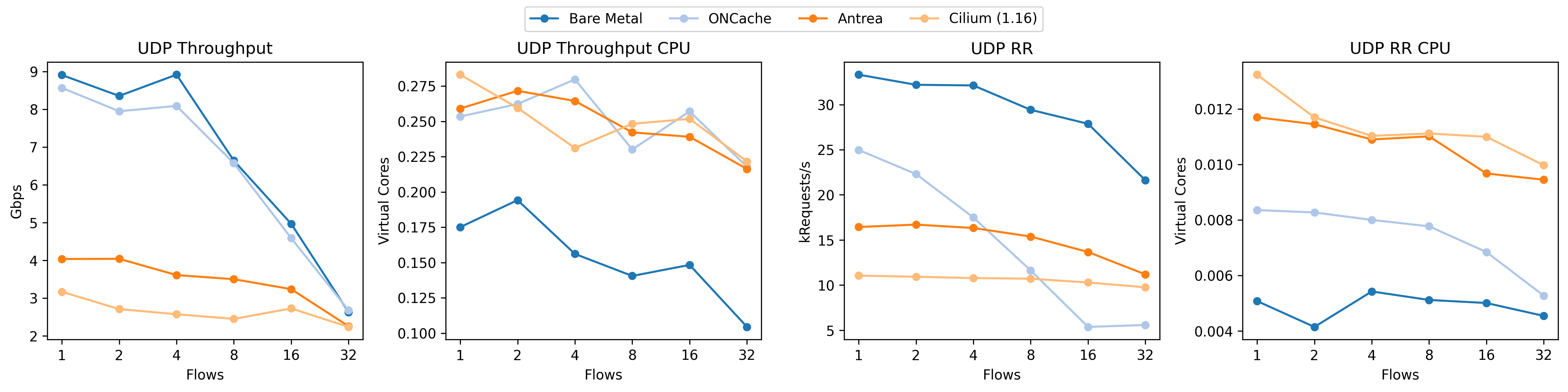
Take a look at how the UDP RR performance (third plot from the left) absolutely tanks for our implementation of ONCache (light blue). Given the shape of the curve, it’s almost a linear falloff (note the exponential axis). For context, this is what we should be seeing:
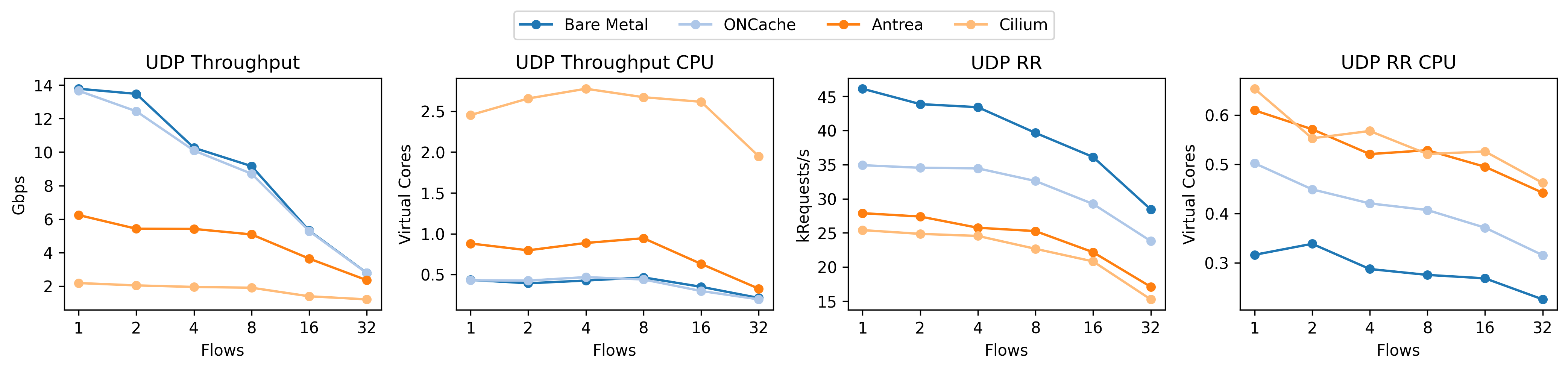
This time, the relative UDP RR performance for ONCache is much better. Note that these plots are from different machines (as I don’t have the bad results from the original benchmark system) but the relative story is still true.
Why is this happening? The linear falloff gives us a bit of a hint; since we have so many cores – more than the number of flows until 32 – a linear falloff implies that we’re not spreading the load across the cores, even though each flow (between a pair of pods) should be using a dedicated core. The short answer is that, from the perspective of the kernel, all of these packets are from the same flow as defined by it’s 4-tuple (source IP, source port, destination IP, and destination port). The kernel uses multiple steering techniques based on the hash of this 4-tuple to spread the load across the cores with hardware (RSS: multiple NIC queues) or software (RPS: core redirection) scaling. The kernel also tries to maintain locality and not just load-balance by steering packets based to applications that previously asked for them (RFS). While we don’t observe these effects in our tests, bad source port selection can also reduce the effectiveness of equal cost multipath routing (ECMP).
So, since our source IP, destination IP, and destination port never change when multiple different pairs of pods are communicating, we need to carefully pick our source port to encourage this load balancing. To effectively “recreate” what the kernel would be doing if these were actual machines communicating, both VXLAN and Geneve specify that the source port should be calculated as a hash of the encapsulated packet’s headers (i.e. hashing the internal 5-tuple). VXLAN specifies that a range of 49152-65535 should be used (based on RFC 6335) while Geneve allows the entire range.12
Conclusion
In this post, we introduced Kubernetes and how it handles networking, focusing on the encapsulation protocols used by overlay networks. We specifically looked at the two most common protocols, VXLAN and Geneve, and how they encapsulate packets for tunneling between machines. We also discussed the importance of correctly selecting UDP source ports to ensure proper load balancing across cores. I hope that this post has given you a solid foundation for understanding Kubernetes networking and the architecture behind these overlay networks. In the next post, we will take a closer look at ONCache, how it achieves its performance improvements, and our replication strategy and results!
Footnotes
-
At least within my concentration of Systems. I don’t know about others like HCI or AI. ↩︎
-
We took this a step further: the ONCache paper has a lot of implementation details in the appendix which we avoided. ↩︎
-
I do not want to deal with reproducing BGP or hardware results, though others have. ↩︎
-
This was typically accomplished via time slices of the CPU as most at the time only had one “core” or processing unit. You can think of it as if one person was on multiple calls and quickly switching between each. ↩︎
-
This is, of course, a major oversimplification of the isolation issue. The general rule is that VMs must fully control the physical resources and can choose whether to share or isolate them. ↩︎
-
Among others; I actually learned about jails first but containers are the dominant tech today. ↩︎
-
Like all good things, there’s an open specification for container runtimes. ↩︎
-
Layer 3 for you OSI model fans. For completeness, some CNI plugins might handle other L3 protocols like ICMP but this research only focuses on IP. ↩︎
-
Layer 4. CNI plugins working at L4 should probably handle the other L4 protocols (especially QUIC) these days but all plugins (that I’m aware of) that support L4 do that for speed and also support L3. ↩︎
-
This is the inner FCS for VXLAN, with Geneve also allowing the omission of the frame preamble, start frame delimiter, and byte alignment rules. In practice (as far as I know), VXLAN implementations follow the Geneve superset. ↩︎
-
We took the easy way out and our reproduction of ONCache treats VXLAN and Geneve as identically-sized headers. ↩︎
-
Both of these approaches are “correct” in a way. VXLAN is being more respectful of the port number ranges as specified in RFC 6335 as the “Dynamic Ports” range of
49152-65535is never assigned by IANA. Geneve, given that it’s specifying itself using its destination port, ignores this for the source port and the entropy gain is probably worth any possible downside. ↩︎